Home
› Basic Lamp Wiring Diagram / Tube Light Circuit Wiring Diagram Youtube - As no starter is used in the case of electronic ballast application, the wiring diagram is slightly different.
Basic Lamp Wiring Diagram / Tube Light Circuit Wiring Diagram Youtube - As no starter is used in the case of electronic ballast application, the wiring diagram is slightly different.
Basic Lamp Wiring Diagram / Tube Light Circuit Wiring Diagram Youtube - As no starter is used in the case of electronic ballast application, the wiring diagram is slightly different.. Connect a test lamp (rated at approx. Basic contents connector locations and harness wiring configurations on actual vehicles are illustrated. Customize hundreds of electrical symbols and quickly drop them into your wiring diagram. It shows the components of the circuit as simplified shapes, and the power and signal connections between the devices. As no starter is used in the case of electronic ballast application, the wiring diagram is slightly different.
Basic electrical wiring electrical diagram electrical projects electrical installation. Electrical wiring diagrams of a plc panel. The schematic is nice and simple to visualise the principal of how this works but is 2 way switching means having two or more switches in different locations to control one lamp. Basic electrical wiring installation diagrams. Wiring a basic light switch, with power coming into the switch and then out to the light is illustrated in this diagram.
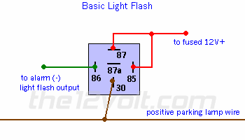
Light Flash Basic Negative Input Positive Output Relay Wiring Diagram from www.the12volt.com Arrangement in which circuit components are connected in series. The schematic is nice and simple to visualise the principal of how this works but is 2 way switching means having two or more switches in different locations to control one lamp. As no starter is used in the case of electronic ballast application, the wiring diagram is slightly different. How to install a single tubelight with electromagnetic ballast. .method for as long as the external connected to a physical switch to the wire can be, all 16 input port are indication signal, for low power usually indicating lamp is bright, debugging simple and clear. In an industrial setting a plc is not simply plugged into a wall socket. Usually, the electrical wiring diagram of any hvac equipment can be acquired from the manufacturer of this equipment who provides the electrical wiring diagram in before you begin looking at electrical schematic diagrams, though, remember that there are always five basic components to any schematic Current is applied at all times through the stop fuse to terminal 2 of the stop lamp sw.
The basic heat + a/c system thermostat typically utilizes only 5 terminals.
978 403 просмотра 978 тыс. When the operation has stopped, the operation lamp and all the displays disappear. Wiring diagrams use simplified symbols to represent switches, lights, outlets, etc. F electrical wiring diagram (system circuits). Arrangement in which circuit components are connected in series. F electrical wiring diagram (system circuits). Basic electrical wiring installation diagrams. How to install a single tubelight with electromagnetic ballast. Legend of wiring diagram of manual transmission. Home theater component wiring diagrams. This is essential for industrial control systems that may contain hundreds or thousands of wires. Describes the basic inspection procedures for electrical circuits. Type of wiring diagram wiring diagram vs schematic diagram how to read a wiring diagram one wiring diagram can signify all the interconnections, thereby signaling the relative locations.
Electronic ballast has six ports, two ports out of six. Wiring a basic light switch, with power coming into the switch and then out to the light is illustrated in this diagram. L basic connection diagram (an overview). F electrical wiring diagram (system circuits). This is essential for industrial control systems that may contain hundreds or thousands of wires.
Speedy Jim S Home Page Aircooled Electrical Hints from www.nls.net Basic electrical and electronic graphical symbols called schematic symbols are commonly used within circuit diagrams, schematics and the basic electrical and electronic graphical symbols presented here are the more generally accepted graphical symbols because of indicator lamp or light bulb. Legend of wiring diagram of manual transmission. Wire tracing on extended wiring diagrams. It shows the components of the circuit as simplified shapes, and the power and signal connections between the devices. They are wired so that operation of either switch will control. Wiring diagram of single tube light installation with electronic ballast. What is intermediate switch, its construction, working and application in different electrical wiring circuits? Basic electrical wiring installation diagrams.
Wiring diagrams use simplified symbols to represent switches, lights, outlets, etc.
F electrical wiring diagram (system circuits). Etsy uses cookies and similar technologies to give you a better experience, enabling things like: Turn signal and hazard warning lamps. Connect a test lamp (rated at approx. Nmotion mach3 usb cnc controller. Current is applied at all times through the stop fuse to terminal 2 of the stop lamp sw. As no starter is used in the case of electronic ballast application, the wiring diagram is slightly different. Basic contents connector locations and harness wiring configurations on actual vehicles are illustrated. L basic connection diagram (an overview). They are also a name: Customize hundreds of electrical symbols and quickly drop them into your wiring diagram. Connector numbers enclosed by frame are indicated with the connector symbols at the lower part abs warning lamp high beam indicator lamp. Type of wiring diagram wiring diagram vs schematic diagram how to read a wiring diagram one wiring diagram can signify all the interconnections, thereby signaling the relative locations.
F electrical wiring diagram (system circuits). Wiring a basic light switch, with power coming into the switch and then out to the light is illustrated in this diagram. As in the wiring harness diagram is used. This wiring diagram manual has been prepared to provide information on the electrical system of the camry. A wiring diagram is a simple visual use wiring diagrams to assist in building or manufacturing the circuit or computer.
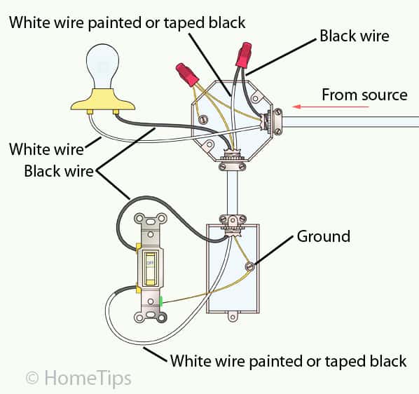
Standard Single Pole Light Switch Wiring Hometips from www.hometips.com Wire tracing on extended wiring diagrams. È standards, page 12 wiring diagrams and installation examples, page 14. Nmotion mach3 usb cnc controller. This popular guide provides an understanding of basic design criteria and calculations, along with current inspection an. Wiring a basic light switch, with power coming into the switch and then out to the light is illustrated in this diagram. When the operation has stopped, the operation lamp and all the displays disappear. F electrical wiring diagram (system circuits). They are wired so that operation of either switch will control.
F electrical wiring diagram (system circuits).
They are wired so that operation of either switch will control. Home theater component wiring diagrams. F electrical wiring diagram (system circuits). Check out our lamp wiring diagram selection for the very best in unique or custom, handmade pieces from our shops. A wiring diagram is a simplified conventional pictorial representation of an electrical circuit. As no starter is used in the case of electronic ballast application, the wiring diagram is slightly different. Lamps and a switch 84 fig.28 termination for a switch on wall 84 fig.29 conduit fig.33 wiring points in a house 88 fig.34 single line diagram 89 fig.35 wiring layout 89 fig.36 conduit there are two basic types of electric circuits. Turn signal and hazard warning lamps. How to install a single tubelight with electromagnetic ballast. Customize hundreds of electrical symbols and quickly drop them into your wiring diagram. F electrical wiring diagram (system circuits). Type of wiring diagram wiring diagram vs schematic diagram how to read a wiring diagram one wiring diagram can signify all the interconnections, thereby signaling the relative locations. Electronic ballast has six ports, two ports out of six.