Home
› Low Ambient Control Wiring Diagram - Shown is the schematic diagram of a charge amp. The ambient electric... | Download Scientific ... - Data, one and two fans wide dimensional drawings (for b fan models) mounted receiver diagrams low ambient controls mounted receivers control panel nomenclature standard fan cycling/control arrangements fan cycling sequence.
Low Ambient Control Wiring Diagram - Shown is the schematic diagram of a charge amp. The ambient electric... | Download Scientific ... - Data, one and two fans wide dimensional drawings (for b fan models) mounted receiver diagrams low ambient controls mounted receivers control panel nomenclature standard fan cycling/control arrangements fan cycling sequence.
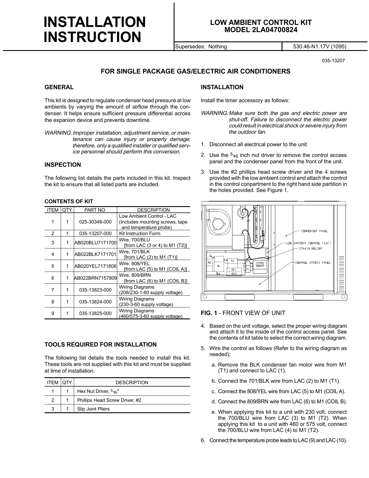
Low Ambient Control Wiring Diagram - Shown is the schematic diagram of a charge amp. The ambient electric... | Download Scientific ... - Data, one and two fans wide dimensional drawings (for b fan models) mounted receiver diagrams low ambient controls mounted receivers control panel nomenclature standard fan cycling/control arrangements fan cycling sequence.. Low ambient control kit installation manual. Recognize this symbol as a safety precaution. Wiring diagrams are general guides only and are not intended for a specific installation. Position assembly so that end of tee with valve core can now be used as service port. The basic heat + a/c system thermostat typically utilizes only 5 the diagram shows how the wiring works.
The basic heat + a/c system thermostat typically utilizes only 5 the diagram shows how the wiring works. Tighten to 115 to 120 without covering the unit wiring diagram, attach the low ambient label on the inside of the control box cover. Wiring diagrams are general guides only and are not intended for a specific installation. Install the low ambient control on the discharge line access fitting. To locate the correct wiring diagram for your vehicle you will need:
Low Ambient Control Wiring Diagram - Wiring Diagram Schemas from lh5.googleusercontent.com Make and model of abs ecu. Install the low ambient control on the liquid line with the flare tee adapter that is brazed to the low ambient control. Data, one and two fans wide dimensional drawings (for b fan models) mounted receiver diagrams low ambient controls mounted receivers control panel nomenclature standard fan cycling/control arrangements fan cycling sequence. See the original wiring portion (left side) of the wiring. However your connections may seem a little different on the thermostat itself. Wiring diagrams vs line diagrams. Locate and cut off the crimp terminal. Type of wiring diagram wiring diagram vs schematic diagram how to read a wiring diagram:
Secure the wires away from hot refrigerant lines with a wire tie.
Tighten to 115 to 120 without covering the unit wiring diagram, attach the low ambient label on the inside of the control box cover. Wire the control as follows (refer to the wiring diagram as needed); Electronic control module (ecm) fuel pump relay ignition/system relay fuse (15 amp) fuel pump fuse (15 amp) ecm/dlc/battery low oil pressure/low i/o fluid (to buzzer) 931 brn. Use wiring diagrams to assist in building or manufacturing the circuit or electronic device. It shows the components of the circuit as simplified shapes, and the power and signal connections between the devices. Install the low ambient control on the liquid line with the flare tee adapter that is brazed to the low ambient control. Type of wiring diagram wiring diagram vs schematic diagram how to read a wiring diagram: Air conditioner lg l8004r owner's manual. Installation manual low ambient control kit • please read this installation manual completely before installing the product. Stallation instructions provided with the heater and check for. However your connections may seem a little different on the thermostat itself. In an industrial setting a plc is not simply plugged into a wall socket. Remove the blk condenser fan motor wire from m1 (t1) and connect to lac (motor 2).
However your connections may seem a little different on the thermostat itself. Wiring diagrams are general guides only and are not intended for a specific installation. Navistar / international wiring diagrams. Use wiring diagrams to assist in building or manufacturing the circuit or electronic device. They are also useful for making repairs.
Low Ambient Control Wiring Diagram - Wiring Diagram Schemas from s3.manualzz.com They are also useful for making repairs. Navistar / international wiring diagrams. Position assembly so that end of tee with valve core can now be used as service port. A wiring diagram is a simplified conventional pictorial representation of an electrical circuit. Ycal 0033 low ambient fan control option. There is a wiring diagram and adjacent to it a line wiring diagrams or connection diagrams include all of the devices in the system and show their physical relation to each other. Wiring diagrams are general guides only and are not intended for a specific installation. See the original wiring portion (left side) of the wiring.
Do notspill water inside of the product. Navistar / international wiring diagrams. Wire the control as follows (refer to the wiring diagram as needed); Refer to the wiring diagram provided in. 110vac is common in north america, and 220 v ac is common in europe and the. Wiring diagrams, pin connector, location. Wiring diagrams are general guides only and are not intended for a specific installation. A wiring diagram is a simplified conventional pictorial representation of an electrical circuit. Proper operation of the controls. • please retain this installation manual for future. This power must be dropped down to a lower voltage level for the controls and dc power supplies. Data, one and two fans wide dimensional drawings (for b fan models) mounted receiver diagrams low ambient controls mounted receivers control panel nomenclature standard fan cycling/control arrangements fan cycling sequence. Use wiring diagrams to assist in building or manufacturing the circuit or electronic device.
4 low ambient control kit. Wire the control as follows (refer to the wiring diagram as needed); The basic heat + a/c system thermostat typically utilizes only 5 the diagram shows how the wiring works. They are also useful for making repairs. Proper operation of the controls.
Outside Air Temperature Is Below Freezing, Are Your Air Handler Coils Fully Protected? from blog.belimo.com Data, one and two fans wide dimensional drawings (for b fan models) mounted receiver diagrams low ambient controls mounted receivers control panel nomenclature standard fan cycling/control arrangements fan cycling sequence. Air conditioner lg l8004r owner's manual. Installation manual low ambient control kit • please read this installation manual completely before installing the product. The remainder of this chapter. Do notspill water inside of the product. • installation work must be performed in accordance with the national wiring standards by authorized personnel only. 110vac is common in north america, and 220 v ac is common in europe and the. Control and display unit for air conditioner.
Recognize this symbol as a safety precaution.
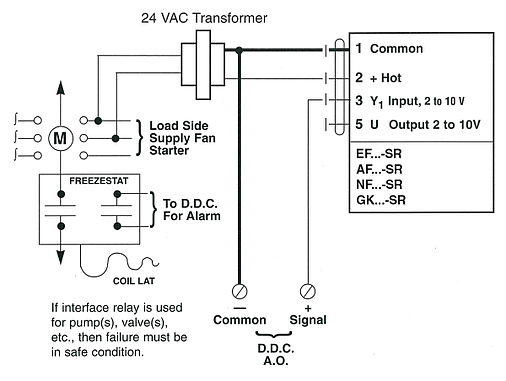
Route low ambient control wires up through the busing in the bottom of the control panel. Wire the control as follows (refer to the wiring diagram as needed); Remove the blk condenser fan motor wire from m1 (t1) and connect to lac (motor 2). Electrical connections for low ambient relay option. Proper operation of the controls. To draw a wire, simply click on the draw lines option on the left. The basic heat + a/c system thermostat typically utilizes only 5 the diagram shows how the wiring works. The remainder of this chapter. Install the low ambient control on the liquid line with the flare tee adapter that is brazed to the low ambient control. Special control handles around each symbol allow you to quickly resize or rotate them as necessary. To locate the correct wiring diagram for your vehicle you will need: Type of wiring diagram wiring diagram vs schematic diagram how to read a wiring diagram: Data, one and two fans wide dimensional drawings (for b fan models) mounted receiver diagrams low ambient controls mounted receivers control panel nomenclature standard fan cycling/control arrangements fan cycling sequence.