Lcd Display Wiring Diagram - Character Lcd 8x1 8x2 8x4 16x1 16x2 20x1 20x2 20x4 24x1 24x2 24x4 32x1 32x2 40x1 40x2 40x4 Pinout And Working - 16×2 lcd with arduino wiring diagram.. It shows the parts of the circuit as streamlined forms, as well as the power and signal connections between the tools. And finally connect the 3.3v of arduino to the a of lcd which is the anode of. The first step in getting the lcd character display working is to wire it up to the arduino. A wiring diagram is a streamlined conventional photographic representation of an electric circuit. In this lcd each character is displayed in a 5×7 pixel matrix.
The controller has an lcd screen for easy programming. It shows the components of the circuit as simplified shapes, and the capacity and signal contacts in the company of the devices. Thers pin lets the microcontroller tell the lcd whether it wants to display that data (as in, an ascii character) or whether it is a command byte (like, change posistion of the cursor). There are a lot of combinations available like, 8×1, 8×2, 10×2, 16×1, etc. It might be neater however, to fit the header pin set and use one of the.
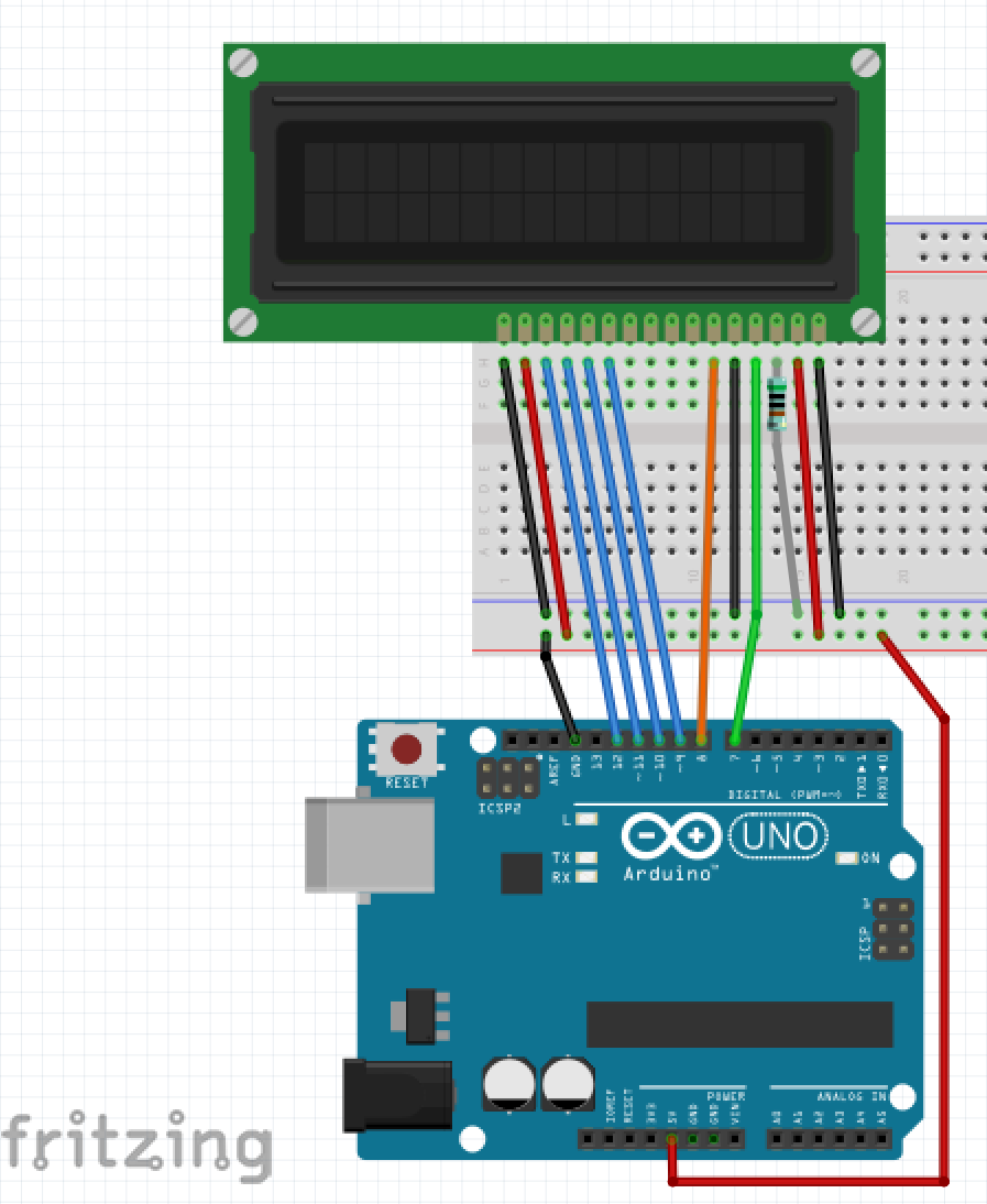
How To Get The Original Lcd Display Working With A New Aftermarket Head Unit In A 2004 Mazda 3 2004 To 2020 Mazda 3 Forum And Mazdaspeed 3 Forums from www.mazda3revolution.com Then, connect the lcd's pin 13 (db6) to the arduino's digital pin 11. Arduino uno, power supply (5v), jhd_162alcd(16x2lcd), 100uf capacitor. Step 1 with the lcd laying flat with the controller board facing up and the brown ribbon cable assembly facing you, locate the dsi ribbon cable connector on the left side of the. The en pin is the 'enable' line we use this to tell the lcd when data is ready for reading. This is a gnd pin of display, used to connect the gnd terminal of the microcontroller unit or power source. Assortment of tft lcd monitor reversing camera wiring diagram. It might be neater however, to fit the header pin set and use one of the. Then connect the digital pin 5 of arduino to the d4 of lcd module.
The video cable connects to the motherboard (or video card) through the connector 1.
Then connect the digital pin 3 of arduino to the d6 of lcd module. The en pin is the 'enable' line we use this to tell the lcd when data is ready for reading. It has 16 columns and 2 rows. The r/w pin is connected to ground, this will pull the pin low and set the lcd to write mode. Connect the lcd's pin 14 (db7) to the arduino's digital pin 12. The lcd display board ships with the display controller board installed onto the back of the lcd panel and has 4 standoffs attached for the raspberry pi to mount to. Basics of lcd displays 2. An lcd is an electronic display module that uses liquid crystal to produce a visible image. I made a bad mistake during replacement of a cracked compaq presario v6000 lcd. Feed and load wiring overview feed wiring mains voltage wiring preferred feed wiring entry for panels with main lugsisolation switch is from the bottom left of the panel. All the above mentioned lcd display will have 16 pins and the programming approach is also the same and hence the choice is left to you. The controller has an lcd screen for easy programming. Arduino uno, power supply (5v), jhd_162alcd(16x2lcd), 100uf capacitor.
16×2 lcd is named so because; If not, the display can potentially present 5v back to the pi which is potentially damaging. A video signal from the motherboard goes to the lcd screen through the video cable. Feed and load wiring overview feed wiring mains voltage wiring preferred feed wiring entry for panels with main lugsisolation switch is from the bottom left of the panel. Electrical wiring diagrams of a plc panel in an industrial setting a plc is not simply plugged into a wall socket.
1 from An lcd is an electronic display module that uses liquid crystal to produce a visible image. If not, the display can potentially present 5v back to the pi which is potentially damaging. It might be neater however, to fit the header pin set and use one of the. Ribbon cable matches dual row connectors, while this display has a single row. Assortment of 7 tft lcd monitor wiring diagram. Once you have wired everything, we can start programming the lcd. Step 1 with the lcd laying flat with the controller board facing up and the brown ribbon cable assembly facing you, locate the dsi ribbon cable connector on the left side of the. Then connect the digital pin 5 of arduino to the d4 of lcd module.
That's it, you've finished wiring up the lcd to the arduino.
Assortment of 7 tft lcd monitor wiring diagram. Before wiring up your lcd to the arduino, make sure that your lcd has the same pin numbering as the one in the circuit diagram below. This is a gnd pin of display, used to connect the gnd terminal of the microcontroller unit or power source. Once you have wired everything, we can start programming the lcd. Wiring the arduino to the lcd display. The wiring diagrams are grouped into individual sections. Ribbon cable matches dual row connectors, while this display has a single row. As for a wiring diagram for the custom made driver board option, you will probably have to do it yourself.(diy, you know) if you are succesful then let us know!! An lcd is an electronic display module that uses liquid crystal to produce a visible image. Some of the customers don't even know that they need to turn the lcd display to operate the kit, so please check this video to follow the steps. And finally connect the 3.3v of arduino to the a of lcd which is the anode of. It has 16 columns and 2 rows. In this illustration we will going to wire the i2c or 2 wire connection in our aruduino board with the 16×2 liquid crystal display, you can also use the 20×4 lcd, but on this demonstration we will going to wire the 16×2 lcd.
I misplaced the ribbon screen wire and after several. Electrical wiring diagrams of a plc panel in an industrial setting a plc is not simply plugged into a wall socket. The controller has an lcd screen for easy programming. In 16x2 lcd there are 16 pins over all if there is a back light, if there is no back light there will be 14 pins. You refer to the diagram of the edge connector on the lcd and use that to hook up the pins on the gpio connector.
Nuevo Foundation Workshops from workshops.nuevofoundation.org It has 16 columns and 2 rows. Wiring the arduino to the lcd display. Electrical wiring diagrams of a plc panel in an industrial setting a plc is not simply plugged into a wall socket. The lcd display board ships with the display controller board installed onto the back of the lcd panel and has 4 standoffs attached for the raspberry pi to mount to. Ribbon cable matches dual row connectors, while this display has a single row. Then connect the digital pin 5 of arduino to the d4 of lcd module. Then connect the digital pin 3 of arduino to the d6 of lcd module. Feed and load wiring overview feed wiring mains voltage wiring preferred feed wiring entry for panels with main lugsisolation switch is from the bottom left of the panel.
A 16×2 lcd display is very basic module and is very commonly used in various devices and circuits.
Feed and load wiring overview feed wiring mains voltage wiring preferred feed wiring entry for panels with main lugsisolation switch is from the bottom left of the panel. 16x2 lcd lcd 16×2 pin diagram. Arduino uno, power supply (5v), jhd_162alcd(16x2lcd), 100uf capacitor. It shows the parts of the circuit as streamlined forms, as well as the power and signal connections between the tools. The 16×2 translates o a display 16 characters per line in 2 such lines. A wiring diagram is a simplified conventional pictorial depiction of an electric circuit. If it does not, you will need to make sure that you make the correct connections between the lcd and arduino. This is a gnd pin of display, used to connect the gnd terminal of the microcontroller unit or power source. And finally connect the 3.3v of arduino to the a of lcd which is the anode of. A wiring diagram is a streamlined conventional photographic representation of an electric circuit. 16×2 lcd with arduino wiring diagram. Electrical wiring diagrams of a plc panel in an industrial setting a plc is not simply plugged into a wall socket. An lcd screen from any laptop and to run it without the laptop,,,don't know which wires on the inverter board to use to hook up power and video to.