Prologic Board Circuit Diagram : Service Manuals :: iPhone 5S Circuit Diagram Schematic Sevice Manual Схема | Circuit diagram ... / 7) replace standoffs onto new board (squeeze back of old board standoffs, move them over) install display.. Request us to beat a competitor's price. It will help you to repair and fault the finding of apple laptops. Replacement pcb main board for aqualogic. 5.1 prologic board or 5.1 pre amp kit audio board and convert 2 channel to 5.1 channel and also use for home theatre sound recorder and sound circuits. Sign up for our newsletter
Plugs for s&d control module, base antenna and cl module. From what i see on the board, one of them is on the path after the relay k6 which is controlled by a 24v dc signal. So there is definitely another source of dc voltage somewhere on the board. Admin may 27, 2021 may 27, 2021 0. Request us to beat a competitor's price.
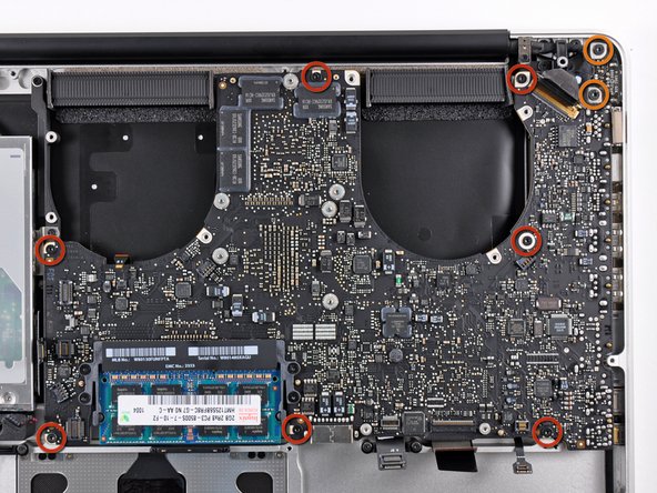
MacBook Pro 15" Unibody Mid 2010 Logic Board Replacement - iFixit Repair Guide from d3nevzfk7ii3be.cloudfront.net Admin may 27, 2021 may 27, 2021 0. The +1.2v powers the core of the fpga. Locate l7130 of ppbus_g3h on the bitmap. This board is the newest board for all pro logic systems made by hayward and goldline controls this will usually fix the no cell power problems. Don't worry here is the best collection of all apple laptop models schematics diagram and boardview. I modified from pro logic i to be pro logic ii audio. You can just add some amplifiers for surround processor fed with this. This was the second board i ordered;
Audio processing from stereo audio signal into surround mode 5.1 channel using chipset ssm2126a from analog devices.
Don't worry here is the best collection of all apple laptop models schematics diagram and boardview. 5.1 prologic board or 5.1 pre amp kit audio board and convert 2 channel to 5.1 channel and also use for home theatre sound recorder and sound circuits. Remove the ssd and wifi module, confirm the board number of the logic board. Main power supplies, +1.2v and +3.3v. Both output in single transformer. Because of the difference in wiring of these earlier boards, the supplied wiring harness must be used. Next, detach the logic board and i/o board from the enclosure, and connect the i/o board to the logic board. 7) replace standoffs onto new board (squeeze back of old board standoffs, move them over) install display. Sign up for our newsletter Stereo 100w amplifier circuit pas4100 prologic shikhman. Replacement pcb main board for aqualogic. This is a high quality dts 5.1 prologic board, a surround sound decoder which converts stereo input to 5.1 channel like front left, front right, center, rear left, rear right and sub. Admin may 27, 2021 may 27, 2021 0.
Both output in single transformer. I modified from pro logic i to be pro logic ii audio. Pro logic board layout diagram. With 5.1 channel audio processor surround pro logic decoder will make the sound come alive like a professional home theater sound system for the distribution of rich sound, and each successive life like a real sound condition. Locate l7130 of ppbus_g3h on the bitmap.
iPhone 5 Schematic Diagram ~ Basic Hardware Tips And Tricks from 3.bp.blogspot.com 5.1 prologic board 5.1 prologic board or 5.1 pre amp kit audio board and convert 2 channel to. From what i see on the board, one of them is on the path after the relay k6 which is controlled by a 24v dc signal. Request us to beat a competitor's price. K1 seems to be the source of power to the display panel but this one as well is controlled by a 24v dc signal which is alway 0v. This is a high quality dts 5.1 prologic board, a surround sound decoder which converts stereo input to 5.1 channel like front left, front right, center, rear left, rear right and sub. G flow monitor (flow switch connector) h p transformer input (120vac x 2) Sign up for our newsletter Plugs for s&d control module, base antenna and cl module.
5.1 prologic board 5.1 prologic board or 5.1 pre amp kit audio board and convert 2 channel to.
Plugs for s&d control module, base antenna and cl module. While the +3.3v powers the input/outputs of the fpga as well as provides. Rev f and earlier aqua logic mainboards: This board is compatible with all date codes. The block diagram shows all of the parts of the dueprologic. Pro logic board layout diagram cell plug dispense power circuit; 2000w class ab power amplifier 2000w class ab power amplifier circuit diagram is the article on circuits99.com explaining 2000w class … read more. Circuit breakers none are included with control—see page 16 and inside of door for suitable breakers wire Both output in single transformer. G flow monitor (flow switch connector) h p transformer input (120vac x 2) Next, detach the logic board and i/o board from the enclosure, and connect the i/o board to the logic board. Plug for the local display. 5.1 prologic board 5.1 prologic board or 5.1 pre amp kit audio board and convert 2 channel to.
With this tone controll is super and amazing output. This is a high quality dts 5.1 prologic board, a surround sound decoder which converts stereo input to 5.1 channel like front left, front right, center, rear left, rear right and sub. Plug for the local display. Main power supplies, +1.2v and +3.3v. Because of the difference in wiring of these earlier boards, the supplied wiring harness must be used.
Macbook Pro A1286 Motherboard Diagram - Diagram Apple Logic Board Diagram Full Version Hd ... from notebookschematic.org (board slips in, and the downward motion to lock in) 6) important: Plugs for s&d control module, base antenna and cl module. Locate l7130 of ppbus_g3h on the bitmap. Plug for the local display. Replace the orange, black, yellow, and red connectors one at a time. Replacement pcb main board for aqualogic. So below is available a table of download links, and it is very easy to download from here. Sign up for our newsletter
Hayward main printed circuit board pcb for goldline controls pro logic and aqua plus control system, all versions, all datecodes.
5.1 prologic board 5.1 prologic board or 5.1 pre amp kit audio board and convert 2 channel to. Check the ddr ram and cpu frequency from the label, roll out the circuit diagram and bitmap. Main power supplies, +1.2v and +3.3v. So below is available a table of download links, and it is very easy to download from here. Remove the ssd and wifi module, confirm the board number of the logic board. Don't worry here is the best collection of all apple laptop models schematics diagram and boardview. Audio output channel as subwoofer, center, fron l, front r, rear l and rear r. Pro logic board layout diagram cell plug dispense power circuit; Pro logic electronics unit (3) temperature sensors with 15 ft. Latest version use this board to upgrade your 2.0 software and to upgrade to the aquapalm. Surely amplifier used is a 6 channel amplifier. This is a high quality dts 5.1 prologic board, a surround sound decoder which converts stereo input to 5.1 channel like front left, front right, center, rear left, rear right and sub. 2000w class ab power amplifier 2000w class ab power amplifier circuit diagram is the article on circuits99.com explaining 2000w class … read more.